A fourth iteration of my 16b CPU family series!
This time with new and exciting features such as:
The project grew out of scope so many times I lost count, world looks much different than it used to back when I started it, and yet the project continues!
This overview is still WIP and will be improved incrementally. For now, the whole article is rather short so I encourage you, dear reader, to read it in full.
Just how hard can it be?
Turns out pretty fucking hard.
This time, I have taken care to make the processor easily runnable form different machines.
All steps necessary to get all code and all tooling on your machine are:
git clone https://github.com/sarvl/16b4x
cd 16b4x
make initfull
And that is it! You should see compilation and running tests.
I still have to set up some flashy example but it is possible to follow my blogs at home.
This is general overview and explanation of some design decisions. For full ISA, see github.
PP EE
ARITHMETIC
      add       d, s/imm8   # R[d] <--  R[d] +  R[s]/ imm16
      and       d, s/imm8   # R[d] <--  R[d] &  R[s]/ imm16
      ann       d, s        # R[d] <--  R[d] & ~R[s]
      cmp       d, s/imm8   #           R[d] -  R[s]/ imm16
   A  dvs       d, s        # R[d] <--  R[d] /  R[s]        ;   signed
   A  dvu       d, s        # R[d] <--  R[d] /  R[s]        ; unsigned
   A  mls       d, s/imm8   # R[d] <--  R[d] *  R[s]/imm16  ;   signed
   A? mlu       d, s/imm8   # R[d] <--  R[d] *  R[s]/imm16  ; unsigned
      neg       d           # R[d] <-- -R[d]
      not       d           # R[d] <-- ~R[d]
      orr       d, s/imm8   # R[d] <--  R[d] |  R[s]/imm16
      shl       d, s/imm8   # R[d] <--  R[d] << R[s]/imm16  ; logical
      shr       d, s/imm8   # R[d] <--  R[d] >> R[s]/imm16  ; logical
      sub       d, s/imm8   # R[d] <--  R[d] -  R[s]/imm16
      tst       d, s/imm8   #           R[d] &  R[s]/imm16
      xor       d, s/imm8   # R[d] <--  R[d] ^  R[s]/imm16
CONTROL FLOW
      cal       s/imm11     # SP <-- SP - 1 ; M[SP] <-- IP ; IP <-- R[s]/(IP + imm16)
      jcc       imm8        # IF(condition) { IP <-- IP + imm16 }
      jmp       imm11       # IP <-- IP + imm16
      ret                   # IP <-- M[SP] ; SP <-- SP + 1
      lop       imm8        # LC <-- LC - 1 ; if(LC >= 0) {IP <-- IP + imm16}
R     hlt                   # halt processor
INTERRUPTS
I?    int       imm8        # raises interrupt imm8
I     irt                   # return from interrupt
INPUT-OUTPUT
O     prd       d, s/imm8   # R[d] <-- P[R[s]]/P[imm16]
O     pwr       d/imm8, s   # P[R[d]]/P[imm16] <-- R[d]
MEMORY
      mrd       d, s/imm8   # R[d] <-- M[R[s]]/M[imm16]
      mwr       d/imm8, s   # M[R[d]]/M[imm16] <-- R[s]
      pop       d           # R[d] <-- M[SP] ; SP <-- SP + 1
      psh       s           # SP <-- SP - 1 ; M[SP] <-- R[s]
      srd       d, imm8     # R[d] <-- M[SP + imm16]
      swr       imm8, s     # M[SP + imm16] <-- R[s]
PERFORMANCE
      prf       s           # prefetch R[s], may be nop
REGISTERS
      scc       d           # IF(condition) {R[d] <-- 1} ELSE {R[d] <-- 0}
      mcc       d, s        # IF(condition) {R[d] <-- R[s]}
      mov       d, s/imm8   # R[d] <-- R[s]/imm16
      xrd       d, s        # R[d] <-- X[s]
      xwr       d, s/imm8   # X[d] <-- R[s]/imm16
CONTROL REGISTERS
C?    crd       d, s/imm5   # R[d] <-- C[R[s]/imm5]
C     cwr       d/imm5, s   # C[R[d]/imm5] <-- R[s]
OTHER
      nop                   # does nothing
   R  rng       d           # R[d] <-- pseudorandom bit pattern

a letter in the P column implies that instruction requires a specific privilege
 a letter followed by '?' implies that instruction MAY require specific privilege, depending on operands
	see [PRIVILEGE_LEVEL]
Letter in E column identifies extension necessary to run the instruction
 a letter followed by '?' implies that instruction has extended functionality if an extension is present
	see [EXTENSIONS]
To fit this many instructions, encoding is more complex than in previous iterations and done in up to 3 stages.
AAAAA is decoded first, most instructions specified by it have 8- or 11-bit immediate, exception to that being conditional moves.
AAAAA = b00001 is reserved for software defined instructions, AAAAA = b00010 contains some privileged instrution, AAAAA = b00010 is reserved for miscelaneous. These instructions are chosen by CCC.
When AAAAA = b00000 then first BBBBB is checked and then CCC.
If BBBBB is 00000 then the instruction is invalid.
This is to prevent uninitialized memory from being executable.
If BBBBB is 00001 to 00011 or above 01000 then instruction is decoded.
Otherwise, one more stage with CCC has to be decoded.
Most instructions have zero extended immediates.
An exception to that are jumps and calls.
Since jumps backward and forward are both often needed, jumps and calls have sign extended immediates.
Also, to reduce the instruction count needed,
For all other cases, there is upper immediate mechanism.
If an instruction is preceeded by
As was hinted, jumps are relative, making them absolute was significant mistake in previous project.
This time it would have been even worse decision, as OS may put a program anywhere in memory.
So, literally
Virtual memory is needed for process isolation without getting into the whole segmentation mess. Implementations can get quite complex with many levels of indirection, especially with larger address spaces. It is one of the things that gets much easier with 16-bit address width.
Here, there is a single layer of translation that turns upper virtual 5 bits into upper physical 10 bits - turning address into 21-bits. It is always on, on boot it is set up to map virtual addresses 1:1 (zero padded) to physical with full rwx permissions. Thanks to this:
Consequently, TLB must always support at least 1 full address space.
For 16bits with 2kiW pages, that is just 32 pages, with 16-bits per translation, that is 512 bits, not nothing but not outrageous.
Page Table is organized as 16 16-bit entries, it can be stored anywhere in 16-bit physical address space. Each entry has: present bit, protected bit, dirty bit, rwx bits, frame id. Note the lack of PID, hardware assumes that page table is for currently running process. Though it might cache different mappings for performance reasons. Therefore any change to page table always requires flush, other than new page addition, even if the process is not currently in use.
There is no need to support cached/uncached pages as IO is done fully through port instructions.
First two features are obvious so I will mostly skip them.
Postfix makes it much easier to implement them.
Simple stack suffices to evaluate all expressions, which saves a ton of work.
For example
For example, the code I use to check
;test xor

%assign $addr {0x1000 1 -}

%assign $iter 0
%rps 2
	%assign $iter {$iter 1 +}

	%assign $a 0

	%rps 5
		%assign $a {$a 1 + 13 *}

		%assign $b 0
		%rps 7
			%assign $b {$b 1 + 7 *}

			%assign $addr {$addr 1 +}

			xwr 	UI, {$a 8 > 0xFF &}
			mov 	R0, {$a 0xFF &}

			%if {$iter 1 =}
				xwr 	UI, {$b 8 > 0xFF &}
				xor 	R0, {$b 0xFF &}
			%else
				xwr 	UI, {$b 8 > 0xFF &}
				mov 	R1, {$b 0xFF &}
				xor 	R0, R1
			%end

			xwr 	UI, {$addr 8 > 0xFF &}
			mwr 	{$addr 0xFF &}, R0
		%rpe
	%rpe
%rpe

	hlt
The code generates 35 pairs of numbers to check, computes their result, and stores it in memory.
This then was compared with golden standard in C and saved as golden standard in tests.
Almost the exact same code executes for other arithmetic operations.
One way to improve it further is to use macros, which are not yet supported.
And the other, which I probably should do, is to add edge case values.
The solution I mentioned above is:
/* defines what each directive has to verify
 * exp = exs ... exe
 * 's' = string
 * 'l' = label
 * 'd' = define
 * 'f' = def | ulb WITH NO DOTS
 * 'r' = var | ulb WITH NO DOTS
 * 'a' = assign
 * 'x' = any
 * 'i' = num | udf | uvr | constant exp
 * 'v' = 'i' | ulb | exp
 * for convenience, each entry is 2 chars
 * but ' ' indicates that no more need to be parsed
 * at any point, mus followed by arg list is a valid token too
 */
constexpr static char const* const pattern_table[] = {
//	 inc, alg, adr, ddw, rps,
	"s ","i ","i ","v ","i ",
//	 rpe, wst, wns, wes, wph, wpp,
	"  ","s ","s ","s ","  ","  ",
//	 def, ass, isd, cif, cel, cen,
	"fi","ri","d ","i ","  ","  ",
//	 cas, inf, war, err  tof, isa
	"vs","s ","s ","s ","x ","a ",
//	 sam  cei  tst, org
	"xx","i ","x ", "i "
	};

const char* pattern = pattern_table[tokens[tid].val];

int const first_line = tokens[tid].line_num;

std::string const pattern_err = [&](){
	std::string ret = "";

	for(int i = 0; i < 3; i++) switch(pattern[i])
	{
	case ' ': return ret;
 	case 's': ret += "STR ";                     continue;
 	case 'f': ret += "ULB/DEF ";                 continue;
 	case 'r': ret += "ULB/VAR ";                 continue;
 	case 'd': ret += "UDF ";                     continue;
 	case 'a': ret += "UVR ";                     continue;
 	case 'x': ret += "ANY ";                     continue;
 	case 'i': ret += "IMM/UDF/UVR/CEX ";         continue;
 	case 'v': ret += "IMM/UDF/UVR/ULB/EXP ";     continue;
	default:  ret += "invalid pattern supplied ";continue;
	}

	return ret;
}();
Later in a for loop, switch case is provided for each letter that tests what is necessary.
This allows to extend and change syntax VERY easily and quickly.
I suspect this is slower than specialized solution and it is definitely harder to generate good error messages.
So for now, I am stuck with I would like to extend this code generation even further, such that specific switch (max performance) is generated from above table (max readability). But this requires ensuring that, indeed, current code is not slow.
Tests cover each stage of processing, making sure that no invalid case passes through.
First, each proper construct is tested to check whether they get turned into accurate lexems.
Bunch of invalid tokens are checked whether they are properly reported.
One test group includes randomly generated
Then, All structures are verified.
Each instruction and directive is checked, not exhaustively but enough to be quite sure of correct behavior.
That means each variant is checked, but values are picked arbitrarily.
Then all preprocessing possibilities are verified, including few invalid kinds.
Finally, all codegen options are verified.
Performance tests are also in the works, though SASM works good enough so it is not a priority.
Error messages are unfortunately part of test system. looking for solutions!
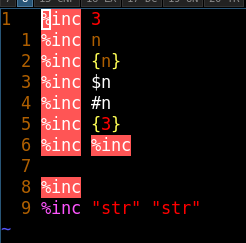
I also added syntax highlight to vim which detects most errors.
This is the simplest subproject.
2 modes are implemented
There is no global state that influences instruction formats so disassembly is trivial. First, decode all possible operands (unused will be ignored). Then switch based on opcode.
I do not think there is generally faster solution, happy to be proven wrong.
Simulator operates in a loop
Instruction is chosen almost exactly in the same fashion as in DASM.
And the path diverges into more files.
This also provides quite convenient way to switch implementation that is used.
To change microarchitecture, replace
All instructions are simple so each case is simple too. Often there are checks for interrupts.
Interrupts are global state that is rised by various events.
As they are presented as synchronous, it does not actually matter whether they are checked or generated asynchronously.
Though it does mean that some interrupts like timer need to be implemented with special care.
Not implemented here, but simulator is generally fast enough and timer slow enough to make ocasional check with
IO is somewhat synchronous, in that it communicates via synchronous instructions.
To be implemented is various performance measurement systems, some TUI debugger, and ultra fast implementation.
Attentious reader might notice lack of tests, they are shared with the CPU and thus covered in tests section
Not much done yet, I do have basic OS working for testing but it is not yet interesting.
The same underlying utility is used for tests but is presented as two separate ones, differentiated by program name.
fost - forensic tester
usage: fost target [args]
	 target is one of {sim, sasm}

by default, nothing is printed, only return code is set

	-h - print this help
	-a - equivalent to -fS
	-A - print everything
	-s - print summary
	-S - print summary pretty, overwrites -s
	-g - print group under test
	-f - print failing tests
	-p - print passing tests
Though, generally all you need to run is === RUNNING TESTS - SIMULATOR === test sim complete total tests : 141 failed tests : 0 time taken : 776ms
Fost is organized such that it is quite easy to add new test target.
It provides easy to use interface for
As said, first writing to memory address is verified, then reading from one. This start requires three instructions to work
Arithmetic instructions are tested with heavy use of metaprogramming to reduce code count. Control flow changes are tested to see whether they do not break. More memory stuff is verified and then the calls. Note that the instruction testing is going back and forth quite a lot, checking X requires knowing that Y works which then requires Z, but logically X and Z are quite similar while Y is completely different. Then a lot of conditional operations are checked.
Then, once we know instructions work, some more elaborate tests are added for the future.
Complex and long dependecy chains, jumps interrupting
Then, few programs are tested just in case.
Finally, IO is tested, as much as it can be in fixed framework anyway.
The low level drives is implemented as FSM wich
Then, on top of that, high level driver works like video card. It holds VRAM and accepts writes to it when low level driver does not read from ram. This is crucial to not require two port RAM. It adds little delay because LL driver most often does not read data, and even if it does it is for one cycle only.
Low level drives implements basic memory interface with no additional fluff. High level one also integrates cache, which for simplicity is always direct mapped write through.
It has been tested by extracting memory operations from few programs
Performance tests are WIP but the results are promising.
I think it could be somewhat improved by clocking it in different domain than the rest of CPU, will have to check.
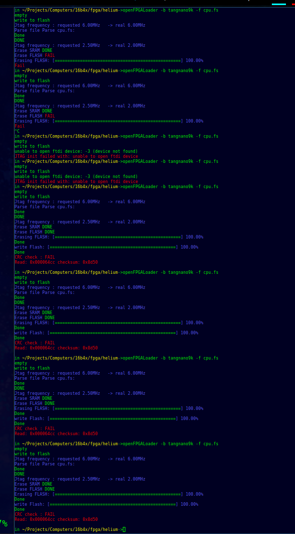
The PSRAM on Tang Nano 9k is borked.
It took me so long to debug it, I am still not entirely certain of that, but all stars point to it being broken.
First
I spent some time reading docs and existing implemenations, planning on what to do, deciding that I should write my own controller because
I decided that it must be an issue with Gowin IDE, so I switched to Yosys (temporarily).
And then, flash started failing.
No idea why it started working again, but it did. I did discover quite a few mistakes in PSRAM controller implementation but it did not solve the issue.
For instance I once wrote a line:
//I suppose it has something to do with how synthesis works... weird stuff
//seven to six? more like six seven
Here is the first of two things that finally convinced me that something is borked with PSRAM.
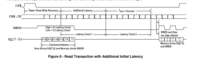
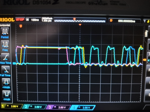
This is a photo of my oscilloscope, with signals:
The second reason was finding github repo with PSRAM controller that had issue mentioning unstability.
https://github.com/zf3/psram-tang-nano-9k/issues/5
This led to 4 possible options:
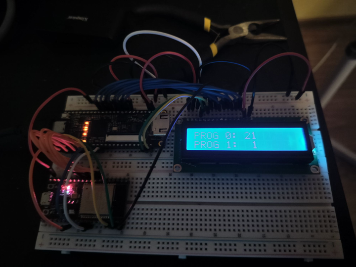
All this, led to finally getting proper output with two programs running in virtual memory!
I have found perfect chip - IDT 71V016, but it is was only SMD. I could have made or buy SMD to THT breakout board, but decided that, while I am at it, might as well make PCB for everything. For more about that, see PCB.
Instead of making it fully on one board, I decided to move memory modules to their own boards. This way in the future I can attach few of the same modules onto single motheboard.
The ram is controlled by by:
The routing is not perfect but I am quite satisfied with it.
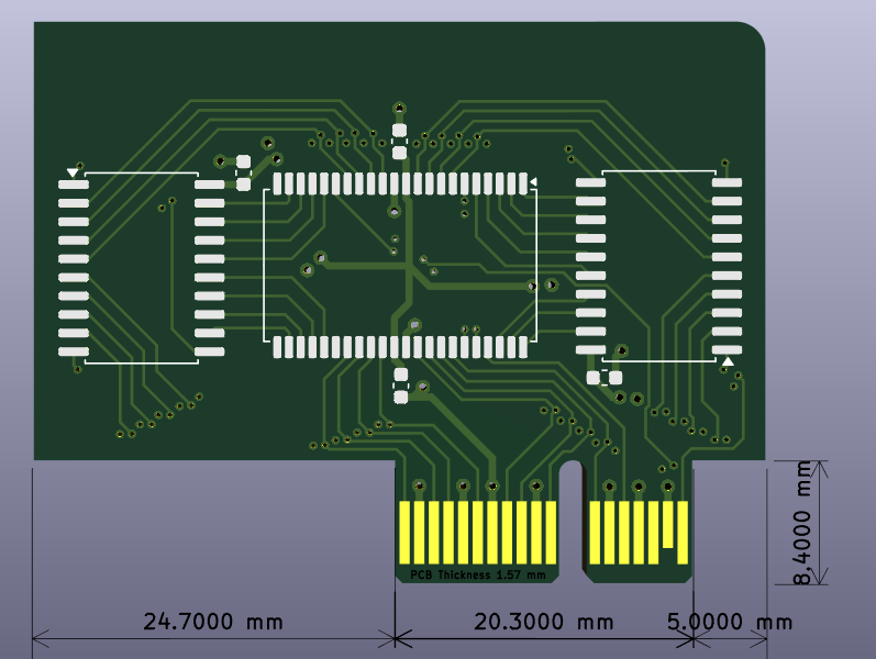
After using it a bit I realized that the connector has slight problem - it scratches and loses connectivity. It is not a big deal, it can be fixed by resoldering fingers. Though it did lead to few weird errors.
But the worst was to come...
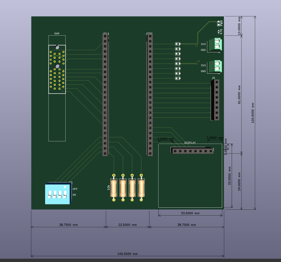
And the worst to come? I flipped the connector. This had to be fixed with wire cutting and some jump wires which were ugly and bad and not nice.
Initially, I planned to improve RAM, but while trying to find its max frequency I realized that my motherboard has no testpoints to properly measure anything, so I fixed that and whatever else was wrong with it instead.
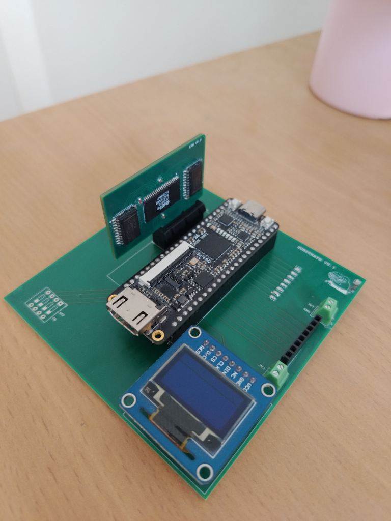
The process was very easy and smooth, boards arrived much earlier than I could receive them so I had to delay the shipment a bit.
I made a small mistake - the PCIe holes were marked as PTH instead of NPTH but still had no copper. This was caught and even fixed by PCBWay.
Once the board arrived, I quickly assembled and soldered everything. All worked - screen screened, ram rammed, and testpoints testpointed.
I did immediattely test the FPGA-RAM communication with testpoints and it works soo well.
The silkscreen is perfect even with small features of apu art.
Though, speaking of silkscreen, some time after the fact I found website mikecoats.com where the author showed neon PCB art supported by PCBWay which looks
One thing that surprised me is it seems that solder sticks to small traces? But they are not conductive on the outside so it is fine.
All in all, I am definitely going to use their services again.
 1. assembler and ISA
	finish instruction formats                                2024-06-28
	convientient to use assembler
		proper error messages
		output controlling
		labels                                                2024-06-29
 2. disassembler to verify everything                         2024-07-01
 3. simulator and ISA                                         2024-07-01
 		simple step through debugger
		memory dump
		regs print
 4. test system
	testing framework
	hijack significant portion of tests from 16b3x            2024-07-01
 5. debugger
 	prints, sets, dumps
	savestate, restorestate                                   2024-07-05
 6. fix things from todo                                      2024-07-05
 7. start writing helium                                      2024-07-07
 	implement entire ISA that does not depend on privilege and VM
	possible ISA adjustements
	figure out external world interface
 8. ISA VM specification and cosi impl                        2024-07-13
 9. write *simple* OS and ISA adjustements
 	some userspace program                                    2024-07-15
10. helium
	implement privilege level, OS, VM
	improve anything required from previous implementation    2024-07-17
11. very general outline of PCB
	~features, layout                                         2024-07-21
12. helium rework
	memory IF
	flash IF
		move OS there
		create bootloader
	make sure design is synthesisable                         2024-08-04
13. assembler improvements
	interface, warning system, format, directives, nested labels
	MANY tests
	docs
	todo fixes                                                2024-08-16
14. PCB
	RAM, MB                                                   2024-08-25
15. ISA updates
	corresponding tool update
	finish instructions, perf counters, system IF             2024-08-28
*********************************************************
***** ~1 year break for various reasons, mostly uni *****
*********************************************************
16. Docs updates
	massive IO and system interface revisions
	put currently unfinilized stuff to freezer                2025-11-05
*********************************************************
*****   on and off working for reasons, mostly uni  *****
*********************************************************
17. Final ISA changes
	update simulator to allow proper supervisor exec          2026-07-25
	better file organization, make init and such, plans       2026-07-31
18. Test system improvements
	unified assembler and simulator test frameworks           2026-08-23
	expanded test framework with test gen                     2026-08-23
	set up VHDL tests for each FPGA component                 2026-08-
	set up FPGA test  for each FPGA component                 2026-08-
19. FPGA peripherals
	lcd screen                                                2026-08-08
	RAM                                                       2026-08-29
	repo cleanup, common types extraction                     2026-09-30
	flash
	leds & switches
further plans are to be disclosed :)